How to Measure a Curved Grader Blade for an Accurate Match
Curved blades are easy to describe badly. A flexible tape follows the arc, while a steel rule measures a straight chord; both readings can be correct and still differ. An accurate match needs named datums and a complete bolt pattern.
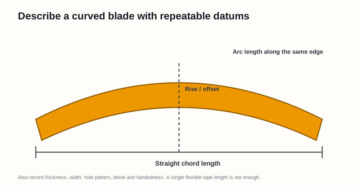
Figure 1. Record straight chord, arc length and rise separately, always from the same reference edge.
Prepare a stable setup
Remove the blade only under the machine’s approved support and lifting procedure. Place it on blocks that prevent rocking without forcing it flat. Clean loose material and burrs, then mark the working edge, top edge, left end and right end.
Record three descriptions of curvature
- Chord length: straight-line distance between two stated end points.
- Arc length: distance along the same curved edge using a flexible tape.
- Rise or offset: maximum perpendicular distance from the chord to the arc.
These three values make the curve far less ambiguous. Also photograph the chord and rise setup from directly above.
Complete dimensional record
| Feature | Recommended method |
|---|---|
| Overall chord | Straight tape/rule between defined ends |
| Arc length | Flexible tape held on the same reference edge |
| Rise | Straightedge across ends plus square/depth measurement |
| Width | Several points, noting worn and unworn zones |
| Thickness | Caliper or micrometer away from burrs |
| Hole diameter | Two directions per representative hole |
| Hole pitch | Multi-hole spans plus adjacent checks |
| End distance | Hole center to each defined end |
| Bevel | Side photograph and angle/template if required |
| Handedness | Installed orientation, not appearance alone |
Measure hole centres efficiently
For equal circular holes, an outside-to-outside span across multiple holes minus one hole diameter gives the first-to-last centre span. Divide by the number of spaces only when the pattern is known to be uniform.
Example: outside span across six equal holes is 1,020 mm and average diameter is 20 mm:
First-to-last centre span = 1,020 − 20 = 1,000 mm
Five equal spaces would be 200 mm, but adjacent pitches must still be checked. Treat every number here as an example, not a grader specification.
Control common errors
- Do not pull a flexible tape across the air and call it arc length.
- Do not force a bent or worn blade flat.
- Do not measure width only at the most worn point.
- Do not assume left and right end distances are equal.
- Do not mix millimetres and inches on one sheet.
- Do not report more decimal places than the tool and surface justify.
NIST measurement guidance emphasizes that equipment, procedure and other sources contribute to dimensional uncertainty. For a field match, consistency and transparent uncertainty are more useful than false precision. See NIST dimensional measurement equipment guidance.
Supplier-ready package
Send the dimension sheet, photographs of every setup, part markings, machine model and serial range, blade position, and whether values come from a worn or new part. If the blade is distorted, state that explicitly rather than averaging the shape into a clean-looking number.
Sources
- NIST: Selecting Dimensional Measurement Equipment
- NIST: Measurement Uncertainty
- Caterpillar: Motor Grader Cutting Edge Replacement Guide
Measurement note: production tolerances and acceptable curvature must come from the applicable drawing or manufacturer.