How to Install a Bolt-On Loader Cutting Edge Correctly
A bolt-on cutting edge depends on uniform contact and clamp load. Dirt, paint, rust scale or a bowed mating surface can settle after the machine returns to work, reducing preload even when every fastener was initially tightened.
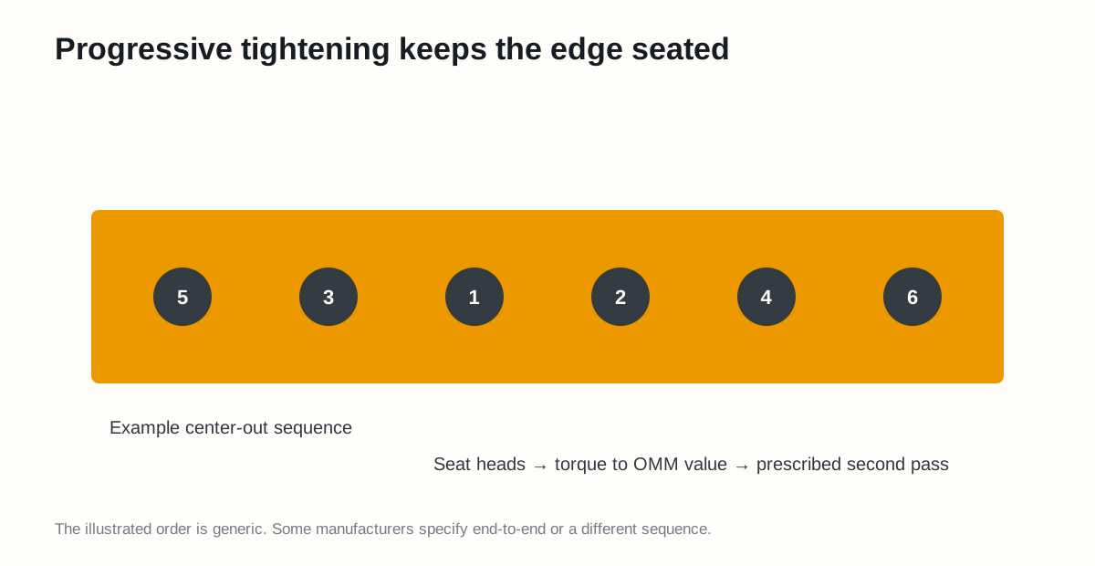
Figure 1. An example centre-out sequence. Use the exact order and torque condition stated by the manufacturer.
Plan the lift and support
Cutting edges are heavy and awkward. Before removal:
- Park on dry, level, stable ground.
- Lower and support the bucket using the approved method.
- Isolate hydraulics and apply the site lockout procedure.
- Determine section weight and select rated lifting equipment.
- Establish an exclusion zone.
- Verify the new edge, hardware, orientation and torque source.
Prepare the joint
After removing one supported section at a time, inspect the bucket base edge for cracks, deformation and elongated holes. Clean both mating surfaces to the condition specified in the OMM.
Caterpillar’s cutting-edge guidance requires surfaces to be free of dirt, paint, scale, rust and weld spatter, and mating surfaces to be clean and flat for maximum clamping force. See Cat Cutting Edge Systems.
Dry-fit before tightening
Position the replacement edge and insert enough specified fasteners by hand to confirm:
- Every hole aligns without forcing
- Countersunk heads seat fully
- Edge and bucket surfaces contact evenly
- Bevel, overlap and end position are correct
- Threads engage smoothly and the correct nut is used
If tightening is required to pull a visible gap closed, stop and find the cause. A bolt is not a press for straightening a damaged base edge.
Progressive tightening
- Install all specified new bolts and nuts loosely.
- Bring the edge into uniform contact using the approved sequence.
- Seat bolt heads by the manufacturer-approved method.
- Tighten with a calibrated tool to the OMM value and stated dry/lubricated condition.
- Complete the prescribed second pass after seating.
- Mark completed fasteners if the site procedure uses torque witness marks.
Caterpillar permits centre-out or end-to-end installation for its referenced cutting edges, instructs users not to lubricate those threads, and calls for tightening again after seating the heads. Do not transfer that dry-thread instruction to a different system that specifies lubricant.
Final checks
- Correct part and orientation
- Full head seating; no proud or rocking heads
- All fasteners present and final pass recorded
- No gaps, trapped debris or cracked structure
- Tools, blocks and loose hardware accounted for
- Follow-up inspection scheduled
Why follow-up matters
Newly cleaned rough surfaces may embed or settle. The OMM or site engineering procedure should define whether and when a post-installation inspection or re-torque is required. Do not create a generic re-torque interval without approval.
Sources
- Caterpillar: Cutting Edge Systems
- Caterpillar: Caring for Precision Cutting Edges
- Caterpillar: Motor Grader Cutting Edge Replacement Guide
Safety note: use the loader OMM for supports, lifting, torque, hardware condition and post-installation checks.