How to Choose Bolts and Nuts for Cutting Edges and Wear Parts
Wear-part hardware is not a bag of interchangeable bolts. The bolt head, shank, thread, nut, coating, joint surfaces and tightening instruction form a matched system. If one element is wrong, the joint may lose clamp load even when the wrench reaches a familiar number.
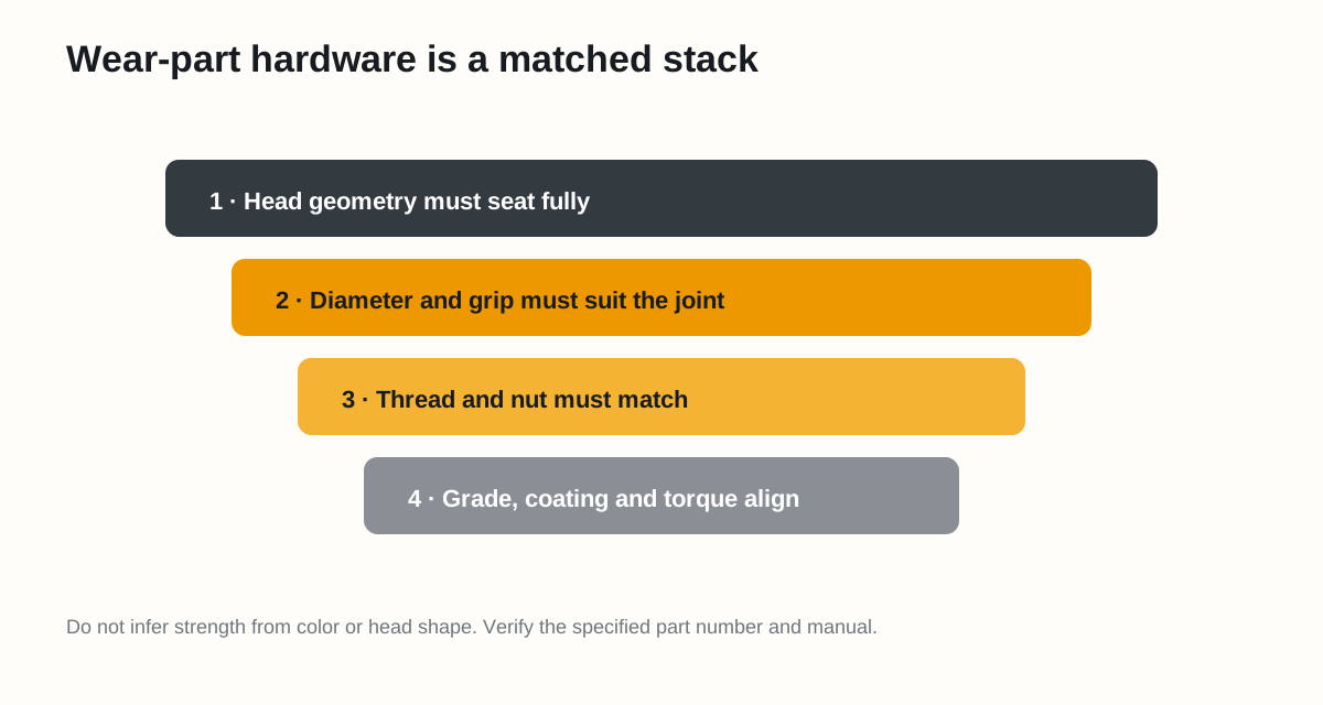
Figure 1. Select the hardware as a stack, beginning with full head seating and ending with the correct torque condition.
Head geometry comes first
Cutting edges commonly use countersunk or plow-style heads so the working face remains smooth. Verify:
- Head diameter and included angle
- Dome, flat or keying geometry
- Square neck, tang or anti-rotation feature
- Full contact in the countersink
- No rocking, bottoming or proud head
A stronger bolt cannot compensate for the wrong head seat. Local contact can damage the hole and allow movement.
Diameter, length and grip
The shank must match the specified hole and pass through the complete joint. Verify the grip length, thread engagement and whether threads are allowed in the shear plane. A bolt that is “long enough” may still have the wrong unthreaded length or bottom in the nut.
ISO 273 provides general-purpose clearance-hole series, but special applications follow their design requirements. Wear parts must therefore match their drawing and fastener specification, not a generic hole chart. See ISO 273.
Thread and nut must match
Confirm:
- Metric or inch system
- Nominal diameter and pitch / threads per inch
- Thread form and hand
- Nut style and prevailing-torque feature, if specified
- Whether the nut is single-use
Never force a near-match. Mixed threads can begin by hand and then damage both parts under power tooling.
Grade and coating are not visual guesses
Use the machine parts information or edge-system specification. Record the complete bolt and nut part numbers. Do not infer strength from color: zinc, phosphate, oxide, paint and site corrosion can look similar, while coatings also affect friction.
NASA’s fastener design guidance and bolted-joint literature emphasize that torque, preload and friction are linked. The same torque can produce a different clamp load when coating or lubrication changes. See the NASA Fastener Design Manual.
Use the correct torque source
The acceptable source is the exact OMM, service manual or approved manufacturer procedure for the hardware condition. Record:
| Item | Required entry |
|---|---|
| Bolt and nut part numbers | Exact identifiers |
| Torque | Value and unit |
| Thread condition | Dry, coated or specified lubricant |
| Tightening sequence | Center-out, end-to-end or specified pattern |
| Seating step | Required method |
| Recheck | Timing or service interval |
Caterpillar instructs users of its referenced cutting-edge systems to use new bolts and nuts, clean surfaces and threads, avoid lubricant, tighten to the required torque, seat heads and tighten again. Apply those statements only to the covered Cat system; other systems may specify a different friction condition. See Cat Cutting Edge Systems.
Reject hardware when
- Threads are rolled, galled, corroded or contaminated
- The head does not seat fully
- The shank is necked or bent
- Markings or part identity cannot be verified
- A prevailing-torque nut no longer meets its reuse rule
- Coating or lubricant differs from the torque instruction
- The mating hole is elongated or cracked
Sources
- Caterpillar: Cutting Edge Systems — hardware tips
- NASA: Fastener Design Manual, RP-1228
- ISO 273: Clearance holes for bolts and screws
Safety note: never substitute a fastener grade, coating, nut or tightening condition without engineering approval.