How to Measure Bolt-Hole Spacing on Wear Parts
A part can have the correct overall length and still be unusable because one hole, pitch or countersink is wrong. A reliable match needs a complete dimensional record and photographs that show how each measurement was taken.
Tools
- Clean steel rule or tape for long spans
- Caliper for hole diameter and thickness
- Straightedge and square
- Thread gauge and known fastener, when safe and appropriate
- Chalk or marker for hole numbering
- Camera and a measurement sheet
Remove burrs and packed material without changing the surface. Measure the part, not a distorted photograph.
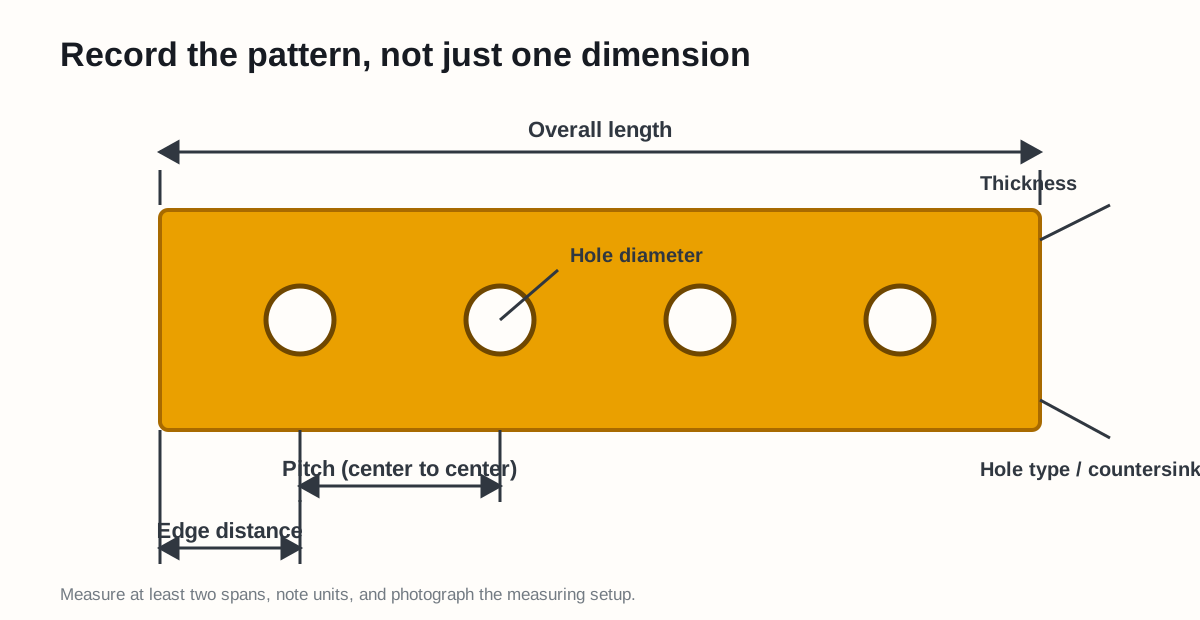
Figure 1. Record overall length, hole diameter, pitch, edge distance, thickness and hole type. The drawing is schematic and not a production specification.
Six dimensions that define the fit
- Overall length and width — measure along straight reference edges.
- Thickness — take several readings away from worn zones and burrs.
- Hole diameter — measure across two directions to detect elongation.
- Pitch — center-to-center spacing between adjacent holes.
- Edge distance — hole center to the nearest reference edge.
- Hole form — plain, countersunk, counterbored, square-neck seat or another profile.
ISO 273 covers clearance-hole diameter series for general-purpose bolts and screws, but special applications are selected from their design requirements. A machinery wear part should therefore be matched to its drawing and fastener system, not inferred from one generic clearance table. See ISO 273:1979.
Find a hole center reliably
For a clean circular hole:
Center position = measured near edge to hole edge + hole diameter ÷ 2
For two holes of equal diameter, you can also measure outside-to-outside and subtract one diameter:
Center distance = outside span − one hole diameter
Or measure inside-to-inside and add one diameter:
Center distance = inside span + one hole diameter
Measure across several holes when possible. If holes 1 through 5 are nominally equally spaced, measure center 1 to center 5 and divide by four. The longer span reduces the effect of small reading errors.
Example
Outside-to-outside span across five equal holes: 824 mm
Average measured hole diameter: 24 mm
Center 1 to center 5: 824 − 24 = 800 mm
Four equal pitches: 800 ÷ 4 = 200 mm
Verify at least one adjacent pitch; do not assume every pattern is uniform.
Estimate measurement uncertainty
Suppose a long-span measurement can vary by ±1 mm and the hole diameter by ±0.2 mm. The calculated center span should not be reported as more precise than the tools support. Record 800 mm (approximately ±1.2 mm) rather than 800.00 mm.
This matters when comparing two candidates whose catalog dimensions differ by only a few millimetres.
Detect damaged holes
Take diameter readings at 0° and 90°. A meaningful difference suggests elongation or damage. Also look for:
- A bolt head that no longer seats fully
- Bright fretting marks around one side of the hole
- Cracks radiating from the hole
- Different pitch readings along the same row
- A plate that bows away from the straightedge
Do not use a damaged hole as the only matching datum. Use several intact holes and the outside geometry, then flag the damage for repair assessment.
A supplier-ready measurement record
| Required item | Example format |
|---|---|
| Units | mm |
| Overall size | 1,524 × 203 × 16 |
| Hole count | 8 |
| Hole diameter | 24.0–24.3 |
| Pitch sequence | 152 / 152 / 152 / … |
| End distance | 78 left / 78 right |
| Hole form | Countersunk; include depth and major diameter |
| Part marking | Exact stamped characters |
| Photos | Front, back, edge, marking, ruler in frame |
Final checks before ordering
- Confirm metric versus inch units.
- Confirm whether dimensions are nominal or measured on a worn part.
- Match the countersink and fastener head, not just the through-hole.
- Verify orientation, curvature and left/right hand.
- Cross-check the machine model, serial range and OEM part number.
Measurement note: all example dimensions are illustrative. Manufacturing acceptance limits must come from the applicable drawing or supplier.